Introduction
Modern data centers represent the pinnacle of fiber optic technology implementation, demanding unprecedented levels of performance, reliability, and scalability. Within these environments, fiber optics is not simply a component—it's the fundamental medium that allows colossal amounts of data to move swiftly and securely between servers, storage arrays, switches, and ultimately, to end-users around the world. As data centers scale to meet exploding bandwidth demands, the role of fiber optics becomes increasingly central, ensuring high-speed connectivity, ultra-low latency, and future-proof infrastructures.
In this comprehensive guide, we will delve deep into the technical intricacies of fiber optic systems in data center settings. We’ll explore how fiber optics evolved to meet these demands, break down the critical technical specifications, examine core and cladding structures, discuss single-mode and multi-mode fibers, and review connector technologies like MPO/MTP that enable massive port densities. We’ll also cover best practices for architecture and design, including how to interpret data center topologies and cross-connect systems. Finally, we’ll walk through installation methodologies, testing and certification procedures, performance optimization strategies, troubleshooting approaches, and emerging trends that will shape the data center fiber optic landscape in the coming decade.
Whether you’re a data center manager aiming to enhance your network’s capacity, a network engineer seeking to understand the nuances of fiber selection, or an industry professional looking to future-proof your deployments, this guide offers the technical insights and strategic considerations you need.
Evolution Timeline
The path from the early days of fiber optics—when attenuation levels were too high for anything but niche applications—to today’s advanced data centers connected by terabit-level fiber links is marked by relentless innovation. Over time, improved glass purity, stable semiconductor lasers, advanced connectors, and dense wavelength division multiplexing (DWDM) have turned fiber optics into a ubiquitous backbone.
Think of this timeline as a continuous journey: from simple fiber lines supporting a few megabits per second, to sophisticated data center interconnects running at 100G, 400G, and soon 800G and 1.6T speeds, each technological step has been essential to scaling digital infrastructures globally.
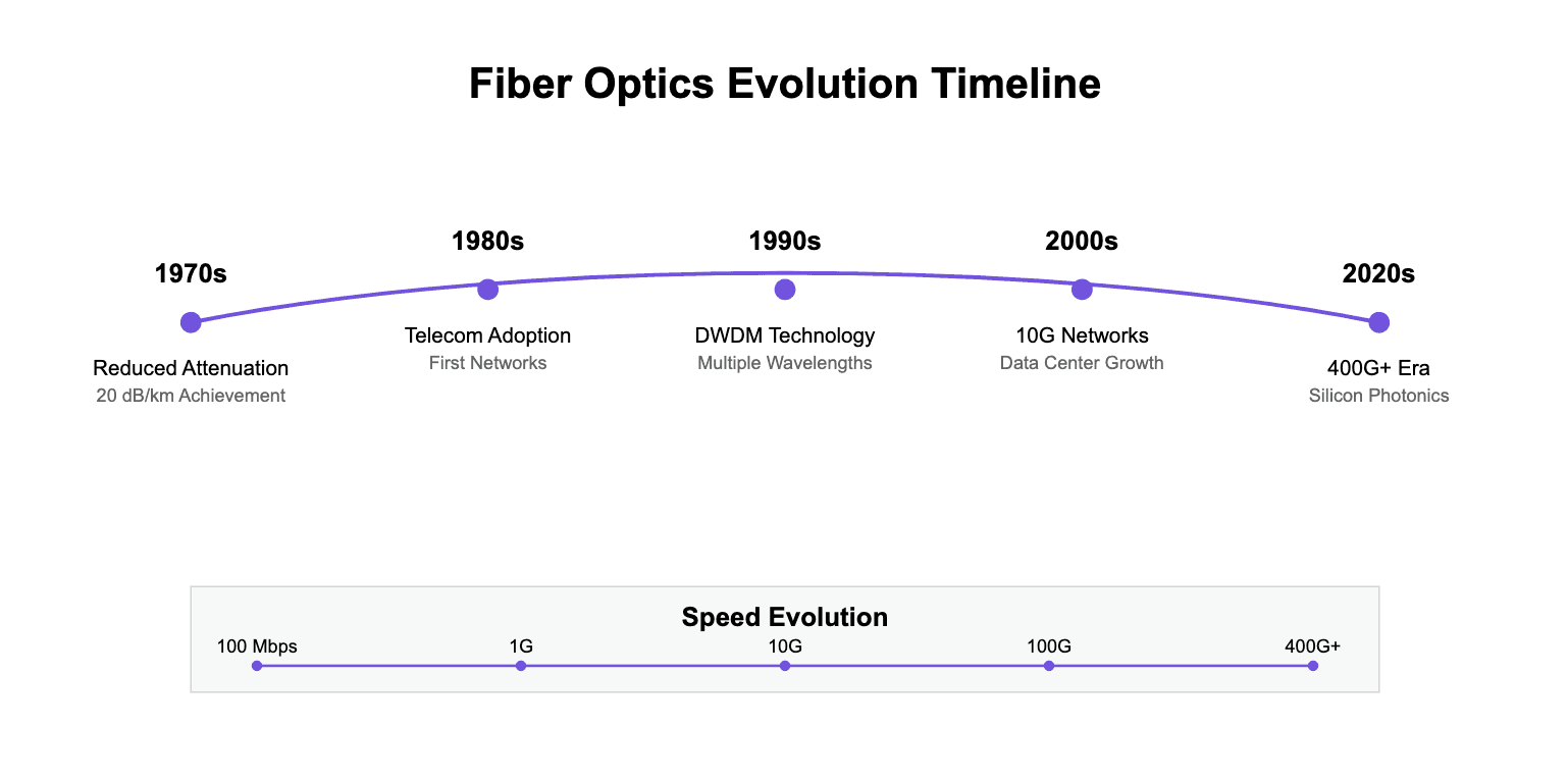
This “Evolution Timeline” illustrate key milestones—such as reductions in fiber attenuation, the introduction of single-mode fibers for long-haul links, the rise of multi-mode fibers in local data center networks, and the deployment of advanced transceivers and co-packaged optics.
Technical Specifications
When deploying fiber optics in data centers, technical specifications matter profoundly. The precise geometry of the core and cladding, the refractive indices involved, and the coatings that protect the fiber against environmental stresses all influence performance metrics like insertion loss, bandwidth capacity, and reliability under high-density cabling conditions.
Fiber Structure Overview
The fundamental structure of a fiber optic cable includes a core (the path where light travels), cladding (which ensures total internal reflection), and one or more protective coating layers.
Core: Typically silica glass, with extreme purity to minimize scattering and absorption.
Cladding: Slightly lower refractive index than the core, ensuring light remains trapped inside.
Buffer Coating & Jacket: Provide mechanical protection, moisture resistance, and durability.
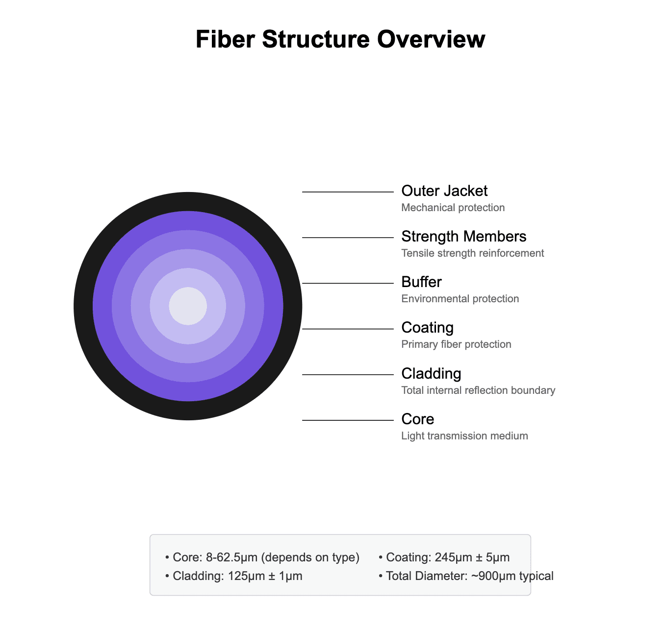
The diagram above illustrates the critical components of fiber optic cables used in data center applications, highlighting the precise engineering required for optimal performance. By visualizing these layers, you appreciate how even minute variations in core diameter or refractive index can impact attenuation and modal dispersion.
Single-Mode Fiber (SMF)
Core Specifications:
Diameter: 9μm ± 0.4μm
Cladding: 125μm ± 0.7μm
Coating: 245μm ± 5μm
Single-mode fiber (SMF) is designed for long-distance, high-bandwidth transmissions. Its narrow core allows only one mode of light to propagate, minimizing modal dispersion and enabling stable performance over kilometers. In data centers, SMF is essential when linking multiple facilities or accommodating extremely high line rates, ensuring low latency and scalability.
Multi-Mode Fiber (MMF)
For shorter distances, multi-mode fiber (MMF) dominates. With a larger core diameter, it supports multiple propagation modes, simplifying the coupling process and enabling the use of less expensive light sources like LEDs or VCSELs.
Technical specifications visualization:
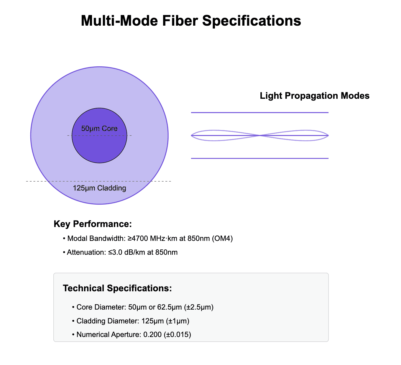
In data centers, MMF typically connects top-of-rack switches to aggregation layers within the same hall. Although its maximum distance is more limited compared to SMF, MMF provides cost-effective solutions for short-reach interconnects, reducing complexity while delivering ample bandwidth for intra-data center traffic.
Connector Technologies
As data centers scale, connecting multiple fibers efficiently becomes a challenge. Traditional LC or SC connectors are suitable for single or dual fiber connections, but data centers often require linking dozens or hundreds of fibers in compact spaces.
MPO/MTP Connector Design:
MPO (Multi-Fiber Push-On) or MTP (a higher-performance MPO variant) connectors house multiple fibers (12, 24, or more) in a single plug. They streamline cable management, minimize rack space usage, and accelerate deployment times.
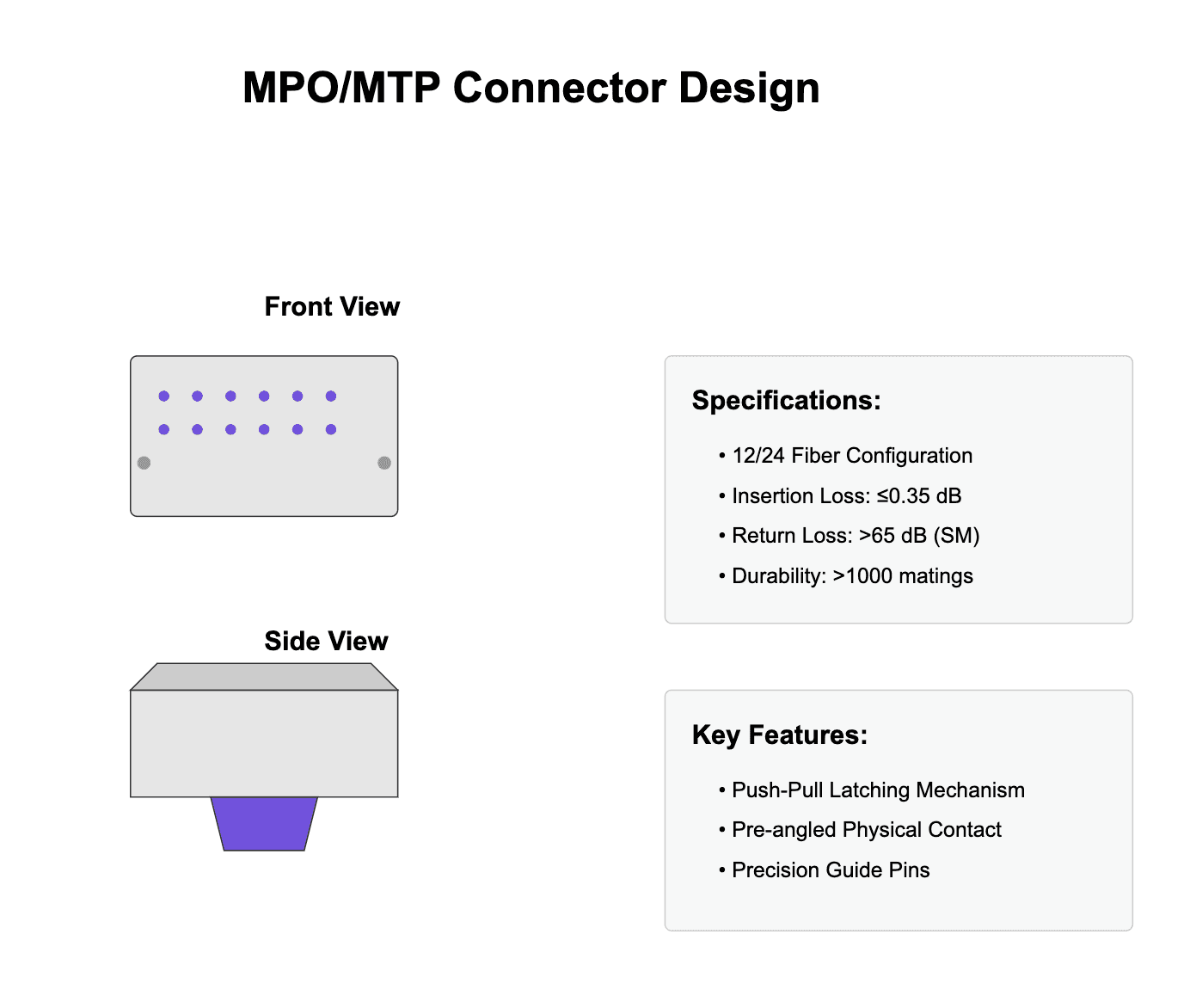
This image would show how MPO/MTP connectors align multiple fibers precisely, ensuring low insertion loss and quick mating/demating for maintenance or upgrades.
Architecture and Design
Data center fiber optics are not deployed randomly; they follow carefully planned architectures that ensure predictable traffic flows, redundant paths, and modular scaling.
Data Center Topology
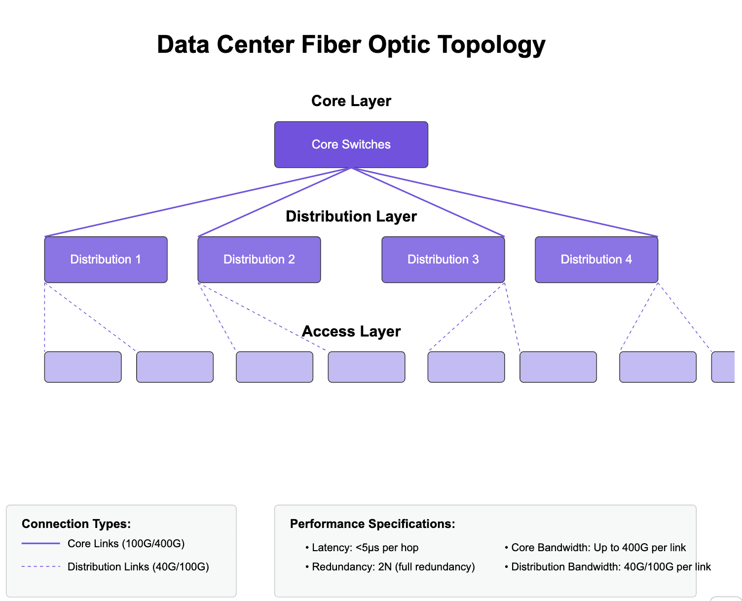
This technical diagram demonstrates the optimal fiber optic cable routing and distribution architecture for modern data centers. You might see a hierarchical model: a Core layer that interconnects multiple Distribution layers, which in turn feed Access layers where servers connect. Each layer uses fiber to ensure high bandwidth and low latency.
Cross-Connect Systems
Cross-connect panels centralize connections, simplifying cable management and allowing technicians to make changes without disturbing active equipment. They often integrate MPO/MTP solutions and modular cassettes that break out trunk cables into multiple LC connections.
">>[INSERT IMAGE: Cross-Connect Systems Diagram]<<"
A diagram here could illustrate a central patching field where multiple trunks converge, making reconfiguration simpler and safer.
Installation Methodology
Proper installation ensures that fiber cables achieve their expected performance. In data centers, where thousands of fibers may be deployed, standards and best practices are crucial.
Cable Installation Process
">>[INSERT IMAGE: Fiber Optic Installation Process]<<"
The diagram above outlines the systematic approach to fiber optic cable installation, highlighting critical quality control points. Steps often include:
Pre-Installation: Verify cable path, ensure no sharp bends, confirm environmental conditions.
Cable Routing: Maintain minimum bend radii (often >30mm), proper pulling tension, and utilize cable trays.
Termination: Install and polish connectors (e.g., MPO/MTP or LC) with precise tolerances.
Testing: Perform OTDR tests, insertion loss measurements, and return loss checks to confirm link integrity before going live.
Testing Setup
Robust testing ensures that every link meets specifications. After all, even a slight insertion loss or reflection beyond thresholds can degrade data center performance.
">>[INSERT IMAGE: Testing Setup Diagram]<<"
This technical illustration shows the proper configuration for comprehensive fiber optic testing and certification. It might depict a power meter and light source arrangement for measuring insertion loss, or a multi-fiber OTDR setup to quickly scan numerous fibers at once.
Performance Optimization
Data centers continually evolve, and what was adequate yesterday might not suffice tomorrow. Performance optimization involves ensuring that signal quality, power budgets, and bandwidth thresholds are not just met, but consistently maintained as traffic grows.
Signal Analysis
Monitoring metrics like optical signal-to-noise ratio (OSNR), bit error rate (BER), and Q-factor helps identify potential issues early. By analyzing these metrics, engineers can proactively adjust transceiver settings, upgrade connectors, or reroute paths.
Loss Budget Analysis
">>[INSERT IMAGE: Loss Budget Analysis Workflow]<<"
The flowchart above details the systematic approach to analyzing and optimizing system performance. It shows how input parameters—link distance, number of connectors, splices, wavelength—feed into calculations of total link loss. If total loss exceeds the system’s power budget, redesigning the link or upgrading components is necessary.
Testing and Certification
Beyond initial installation, testing must be a continuous practice. Upgrades, relocations, and expansions demand reconfirmation of fiber integrity.
OTDR Testing Configuration
">>[INSERT IMAGE: OTDR Testing Configuration]<<"
This diagram illustrates the proper setup for OTDR testing, including launch cables and measurement points. An OTDR sends short pulses of light and analyzes backscatter to identify faults, measure length, and verify that no unexpected losses occur mid-span. Careful interpretation of OTDR traces can reveal tiny cracks, microbends, or poorly polished connectors.
Performance Verification Process
Data center operators may conduct periodic checks, comparing current link performance against baseline results. Automation and AI-driven analytics can accelerate this verification, highlighting deviations instantly.
Troubleshooting Guide
Even the best-planned networks encounter issues. Whether from accidental cable damage, connector contamination, or equipment failure, troubleshooting must be systematic to minimize downtime.
Systematic Problem Resolution
">>[INSERT IMAGE: Fiber Optic System Troubleshooting Guide]<<"
This flowchart provides a structured approach to identifying and resolving fiber optic system issues. Determine if the problem is high loss, high reflection, or complete signal loss, then follow targeted steps—clean connectors, repolish ends, verify continuity, or adjust mating pressure—until the link is restored.
Advanced Diagnostic Tools
In critical scenarios, high-resolution OTDR scans, connector end-face microscopes, and real-time monitoring systems offer deeper insight. They let engineers pinpoint subtle issues not visible through basic tests.
Industry Applications
Data center fiber optics aren’t confined to generic web hosting. Specialized environments, like HPC clusters or cloud computing platforms, stretch fiber requirements further, demanding extreme bandwidth, minimal latency, and robust fault tolerance.
High-Performance Computing Implementation
">>[INSERT IMAGE: HPC Implementation Diagram]<<"
This technical diagram shows the optimal fiber optic configuration for high-performance computing environments. It might depict clusters interconnected by ultra-low-latency fibers, redundant paths to storage arrays, and multiple 400G/800G links aggregated into a single HPC fabric.
Cloud Computing Architecture
In multi-tenant cloud platforms, fiber optics ensure on-demand provisioning. Rapid scaling, load balancing, and high availability all depend on consistent fiber quality and bandwidth headroom. Hybrid cloud strategies often link private and public data centers with long-haul fibers, ensuring seamless data mobility.
Future Considerations
As we look ahead, the next decade promises radical changes. Emerging fiber technologies, integrated photonics, and AI-driven management will reshape data centers yet again.
Next-Generation Technologies
">>[INSERT IMAGE: Emerging Fiber Optic Technologies: 2025-2030]<<"
This visualization outlines emerging fiber optic technologies and their potential impact on data center design. Hollow-core fibers promise lower latency and new bandwidth regimes, multi-core fibers pack multiple pathways into one strand, silicon photonics integrate transceivers on-chip, and AI/ML infrastructures self-optimize routing, maintenance, and performance.
Implementation Planning
Planning for these advances involves anticipating line rate growth (400G to 800G, 1.6T), considering the ROI of early silicon photonics adoption, and ensuring that cable management systems can handle new form factors and connector standards.
Conclusion
The successful implementation of fiber optic systems in data center environments requires comprehensive technical understanding, from the fundamental properties of single-mode and multi-mode fibers to the intricacies of MPO/MTP connectors, loss budget calculations, OTDR testing setups, and performance optimization strategies. As data centers evolve, incorporating advanced HPC architectures, cloud-based scaling, and next-generation fibers, the complexity grows—but so do the opportunities to achieve unprecedented efficiency, reliability, and speed.
Contact our engineering team for detailed consultation on your specific requirements. Whether upgrading an existing data center to handle new workloads or designing a state-of-the-art HPC environment, leveraging the right fiber optic solutions will ensure a future-proof, high-performing infrastructure.
Technical Resources
Building and optimizing your data center fiber infrastructure often involves using specialized tools and references. Fiberoptic Systems Inc. provides an array of resources:
Fiber Optic Loss Calculator:
Quickly estimate insertion loss and verify link budgets.Optical Parameter Converter:
Convert units, wavelengths, and optical parameters with ease.Technical Specifications:
Consult detailed datasheets and engineering notes on fiber, connectors, and assemblies.Custom Solutions:
If your data center needs demand unique wavelength ranges, specific bend tolerances, biocompatibility, or extreme temperature resistance, we can customize assemblies accordingly.Industry Applications:
Explore case studies and examples of how fiber optics enhance healthcare, industrial automation, telecommunications, and defense systems. Understanding cross-industry lessons helps drive data center innovation.
End with a final thought:
By integrating the best practices, methodologies, and insights presented here—and by utilizing the attached diagrams and images placed in quotes for easy insertion—you can confidently advance your data center fiber optic strategies. As technology evolves, your proactive understanding of fiber optics will position you to capitalize on emerging opportunities and maintain a resilient, high-performance data center environment.


