FSI
dB Converter
Results:

dB (Decibel) Conversions in Transmission (Tx) Systems
Introduction
In the world of telecommunications, electronics, and particularly fiber optics, the decibel (dB) is a fundamental unit used to express ratios of power, voltage, or intensity. Understanding how to convert between linear values (like power in watts) and decibels is crucial for designing, analyzing, and troubleshooting transmission systems.
This guide will walk you through the concepts of decibel calculations, provide interactive tools for quick conversions, and demonstrate how these principles apply to real-world scenarios in fiber optic systems. Whether you're a seasoned engineer or a student just beginning to explore the field, mastering dB conversions will significantly enhance your ability to work with optical and electrical systems effectively.
Let's dive into the world of decibels and discover how this logarithmic unit simplifies calculations and provides invaluable insights into signal strength, attenuation, and amplification in transmission systems.
What is a Decibel (dB)?
A decibel (dB) is a logarithmic unit used to express the ratio between two values, typically power or amplitude. It's named after Alexander Graham Bell and is one-tenth of a bel (B), a unit that proved too large for practical use.
Key characteristics of the decibel:
It's a dimensionless unit, expressing a ratio rather than an absolute value.
It uses a logarithmic scale, which allows for a wide range of values to be expressed in a manageable form.
It's additive for power ratios, simplifying calculations involving multiple gains or losses.
Why Use Decibels?
Managing Large Variations: In transmission systems, signal levels can vary by factors of millions or billions. Decibels compress this huge range into more manageable numbers. For example, a power ratio of 1,000,000:1 is simply 60 dB.
Simplifying Multiplicative Processes: In a transmission system, signals often undergo multiple stages of amplification or attenuation. With decibels, these multiplicative processes become simple addition or subtraction.
Matching Human Perception: Our perception of sound and light intensity is roughly logarithmic. Decibels align well with how we perceive changes in signal strength.
Industry Standard: Using decibels allows for easy communication and comparison across different systems and technologies.
Ease of Calculation: When dealing with very large or very small numbers, decibel calculations can be easier and less error-prone than working with linear values.
By understanding and using decibels, engineers and technicians can more intuitively grasp signal changes, design systems more effectively, and communicate specifications more clearly.
dB Conversion Formulas
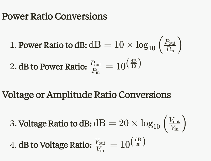
Power Ratio Conversions
Power Ratio to dB: dB=10×log10(PoutPin)\text{dB} = 10 \times \log_{10}\left(\frac{P_{\text{out}}}{P_{\text{in}}}\right)dB=10×log10(PinPout)
dB to Power Ratio: PoutPin=10(dB10)\frac{P_{\text{out}}}{P_{\text{in}}} = 10^{\left(\frac{\text{dB}}{10}\right)}PinPout=10(10dB)
Voltage or Amplitude Ratio Conversions
Voltage Ratio to dB: dB=20×log10(VoutVin)\text{dB} = 20 \times \log_{10}\left(\frac{V_{\text{out}}}{V_{\text{in}}}\right)dB=20×log10(VinVout)
dB to Voltage Ratio: VoutVin=10(dB20)\frac{V_{\text{out}}}{V_{\text{in}}} = 10^{\left(\frac{\text{dB}}{20}\right)}VinVout=10(20dB)
Note: The voltage/amplitude formulas assume equal impedances. For situations with different input and output impedances, additional calculations are necessary.
These formulas form the basis of our dB conversion calculators and are essential for analyzing signal levels in transmission systems.
Interactive dB Calculators
Our interactive dB calculators allow you to quickly convert between linear ratios and decibels for both power and voltage/amplitude. Here's how to use them:
Power Ratio Conversions
Power Ratio to dB:
Input: Enter the power ratio (P_out / P_in) in the first field.
Output: The calculator will display the corresponding dB value.
dB to Power Ratio:
Input: Enter the dB value in the second field.
Output: The calculator will display the corresponding power ratio.
Voltage Ratio Conversions
Voltage Ratio to dB:
Input: Enter the voltage ratio (V_out / V_in) in the third field.
Output: The calculator will display the corresponding dB value.
dB to Voltage Ratio:
Input: Enter the dB value in the fourth field.
Output: The calculator will display the corresponding voltage ratio.
Using the Calculators
Enter values in any input field to see real-time results in the corresponding output field.
For ratio inputs (power and voltage), use positive numbers only.
For dB inputs, any real number is acceptable.
Results are displayed with two decimal places for dB values and four decimal places for ratios.
Example Calculations
Power Ratio to dB:
Input: 2 (representing a doubling of power)
Output: 3.01 dB
dB to Power Ratio:
Input: -3 dB
Output: 0.5012 (representing approximately half power)
Voltage Ratio to dB:
Input: 2 (representing a doubling of voltage)
Output: 6.02 dB
dB to Voltage Ratio:
Input: -6 dB
Output: 0.5012 (representing approximately half voltage)
Interpreting Results
Positive dB values indicate a gain or increase in power/voltage.
Negative dB values indicate a loss or decrease in power/voltage.
A 3 dB change represents approximately a doubling (gain) or halving (loss) of power.
A 6 dB change represents approximately a doubling (gain) or halving (loss) of voltage.
Remember, these calculators assume equal impedances for voltage conversions. For more complex scenarios involving changing impedances, additional calculations may be necessary.
Practical Applications in Fiber Optics
Understanding dB conversions is crucial in fiber optic systems. Here are some practical applications:
1. Fiber Attenuation
Fiber optic cables experience signal loss over distance, typically measured in dB/km.
Example: A single-mode fiber has an attenuation of 0.3 dB/km at 1550 nm. For a 50 km link:
Total attenuation = 0.3 dB/km × 50 km = 15 dB
Power ratio = 10^(-15/10) ≈ 0.0316
This means only about 3.16% of the input power reaches the end of the 50 km fiber.
2. Optical Amplifier Gain
Optical amplifiers boost signal power, often specified in dB.
Example: An Erbium Doped Fiber Amplifier (EDFA) provides 20 dB gain.
Power ratio = 10^(20/10) = 100
This amplifier increases the signal power by a factor of 100.
3. Connector and Splice Losses
Each connector or splice in a fiber system introduces some loss.
Example: A system has 6 connectors, each with a 0.5 dB loss.
Total connector loss = 6 × 0.5 dB = 3 dB
Power ratio = 10^(-3/10) ≈ 0.5012
About 50.12% of power is transmitted through all connectors.
4. Optical Power Budget
Calculating the power budget ensures sufficient signal strength at the receiver.
Example:
Transmitter power: +3 dBm
Fiber attenuation: -15 dB (from example 1)
Connector losses: -3 dB (from example 3)
Amplifier gain: +20 dB (from example 2)
Receiver sensitivity: -20 dBm
Power budget calculation: 3 dBm - 15 dB - 3 dB + 20 dB = 5 dBm at receiver
Since 5 dBm > -20 dBm (receiver sensitivity), the link is viable.
5. Optical Return Loss (ORL)
ORL measures the total amount of light reflected back to the source.
Example: A fiber link has an ORL of 40 dB.
Reflection ratio = 10^(-40/10) = 0.0001
Only 0.01% of the light is reflected back, indicating a good connection.
These examples demonstrate how dB calculations are integral to designing, troubleshooting, and optimizing fiber optic systems. By mastering these conversions, you can effectively analyze and improve optical network performance.
Key Points to Remember About dB Conversions
Logarithmic Nature:
dB is a logarithmic unit, compressing large ranges into manageable numbers.
Small dB changes can represent significant linear changes.
Power vs. Voltage:
For power ratios, use 10 log₁₀(P₂/P₁)
For voltage ratios, use 20 log₁₀(V₂/V₁)
Gain vs. Loss:
Positive dB values indicate gain or increase.
Negative dB values indicate loss or decrease.
Common dB Values:
3 dB ≈ doubling or halving of power
6 dB ≈ doubling or halving of voltage
10 dB = 10 times power change
20 dB = 100 times power change
Addition vs. Multiplication:
In dB, gains/losses are added, not multiplied.
Example: 3 dB + 3 dB = 6 dB (4x power), not 9 dB
Absolute vs. Relative:
dB is a relative measure (ratio between two values).
dBm is an absolute measure (relative to 1 mW).
Fiber Optic Applications:
Attenuation often expressed in dB/km
Connector losses typically 0.3-0.5 dB each
Amplifier gains commonly 20-30 dB
Calculation Tips:
Use a calculator for precise values.
Round to 1 decimal place for most practical applications.
System Analysis:
Sum all gains and losses in dB for total system impact.
Compare final signal level to receiver sensitivity.
Conversion Accuracy:
When converting between dB and linear, maintain sufficient decimal places to avoid compounding rounding errors.
Remember, proficiency with dB conversions comes with practice. Regular use of these concepts in real-world scenarios will reinforce your understanding and intuition.
Conclusion
Mastering dB conversions is an essential skill for anyone working with transmission systems, especially in the field of fiber optics. The ability to quickly and accurately convert between linear ratios and decibels allows you to:
Efficiently analyze signal levels throughout a system
Easily calculate total gains and losses
Communicate system specifications clearly and concisely
Make informed decisions about component selection and system design
As you've seen through the practical examples, dB calculations are integral to every aspect of fiber optic system design and maintenance, from calculating fiber attenuation to determining optical power budgets.
The interactive calculators provided here serve as valuable tools for quick conversions, but remember that true proficiency comes with practice and application. We encourage you to use these concepts regularly in your work or studies, and to explore further the many applications of dB calculations in your specific area of interest.
Whether you're designing a new fiber optic network, troubleshooting an existing system, or simply striving to deepen your understanding of transmission technologies, a solid grasp of dB conversions will prove invaluable.
Continue to explore, practice, and apply these principles, and you'll find yourself navigating the world of signal levels and transmission systems with increasing confidence and expertise.
dB (Decibel) Conversions in Transmission (Tx) Systems
Introduction
In the world of telecommunications, electronics, and particularly fiber optics, the decibel (dB) is a fundamental unit used to express ratios of power, voltage, or intensity. Understanding how to convert between linear values (like power in watts) and decibels is crucial for designing, analyzing, and troubleshooting transmission systems.
This guide will walk you through the concepts of decibel calculations, provide interactive tools for quick conversions, and demonstrate how these principles apply to real-world scenarios in fiber optic systems. Whether you're a seasoned engineer or a student just beginning to explore the field, mastering dB conversions will significantly enhance your ability to work with optical and electrical systems effectively.
Let's dive into the world of decibels and discover how this logarithmic unit simplifies calculations and provides invaluable insights into signal strength, attenuation, and amplification in transmission systems.
What is a Decibel (dB)?
A decibel (dB) is a logarithmic unit used to express the ratio between two values, typically power or amplitude. It's named after Alexander Graham Bell and is one-tenth of a bel (B), a unit that proved too large for practical use.
Key characteristics of the decibel:
It's a dimensionless unit, expressing a ratio rather than an absolute value.
It uses a logarithmic scale, which allows for a wide range of values to be expressed in a manageable form.
It's additive for power ratios, simplifying calculations involving multiple gains or losses.
Why Use Decibels?
Managing Large Variations: In transmission systems, signal levels can vary by factors of millions or billions. Decibels compress this huge range into more manageable numbers. For example, a power ratio of 1,000,000:1 is simply 60 dB.
Simplifying Multiplicative Processes: In a transmission system, signals often undergo multiple stages of amplification or attenuation. With decibels, these multiplicative processes become simple addition or subtraction.
Matching Human Perception: Our perception of sound and light intensity is roughly logarithmic. Decibels align well with how we perceive changes in signal strength.
Industry Standard: Using decibels allows for easy communication and comparison across different systems and technologies.
Ease of Calculation: When dealing with very large or very small numbers, decibel calculations can be easier and less error-prone than working with linear values.
By understanding and using decibels, engineers and technicians can more intuitively grasp signal changes, design systems more effectively, and communicate specifications more clearly.
dB Conversion Formulas
Power Ratio Conversions
Power Ratio to dB: dB=10×log10(PoutPin)\text{dB} = 10 \times \log_{10}\left(\frac{P_{\text{out}}}{P_{\text{in}}}\right)dB=10×log10(PinPout)
dB to Power Ratio: PoutPin=10(dB10)\frac{P_{\text{out}}}{P_{\text{in}}} = 10^{\left(\frac{\text{dB}}{10}\right)}PinPout=10(10dB)
Voltage or Amplitude Ratio Conversions
Voltage Ratio to dB: dB=20×log10(VoutVin)\text{dB} = 20 \times \log_{10}\left(\frac{V_{\text{out}}}{V_{\text{in}}}\right)dB=20×log10(VinVout)
dB to Voltage Ratio: VoutVin=10(dB20)\frac{V_{\text{out}}}{V_{\text{in}}} = 10^{\left(\frac{\text{dB}}{20}\right)}VinVout=10(20dB)
Note: The voltage/amplitude formulas assume equal impedances. For situations with different input and output impedances, additional calculations are necessary.
These formulas form the basis of our dB conversion calculators and are essential for analyzing signal levels in transmission systems.
Interactive dB Calculators
Our interactive dB calculators allow you to quickly convert between linear ratios and decibels for both power and voltage/amplitude. Here's how to use them:
Power Ratio Conversions
Power Ratio to dB:
Input: Enter the power ratio (P_out / P_in) in the first field.
Output: The calculator will display the corresponding dB value.
dB to Power Ratio:
Input: Enter the dB value in the second field.
Output: The calculator will display the corresponding power ratio.
Voltage Ratio Conversions
Voltage Ratio to dB:
Input: Enter the voltage ratio (V_out / V_in) in the third field.
Output: The calculator will display the corresponding dB value.
dB to Voltage Ratio:
Input: Enter the dB value in the fourth field.
Output: The calculator will display the corresponding voltage ratio.
Using the Calculators
Enter values in any input field to see real-time results in the corresponding output field.
For ratio inputs (power and voltage), use positive numbers only.
For dB inputs, any real number is acceptable.
Results are displayed with two decimal places for dB values and four decimal places for ratios.
Example Calculations
Power Ratio to dB:
Input: 2 (representing a doubling of power)
Output: 3.01 dB
dB to Power Ratio:
Input: -3 dB
Output: 0.5012 (representing approximately half power)
Voltage Ratio to dB:
Input: 2 (representing a doubling of voltage)
Output: 6.02 dB
dB to Voltage Ratio:
Input: -6 dB
Output: 0.5012 (representing approximately half voltage)
Interpreting Results
Positive dB values indicate a gain or increase in power/voltage.
Negative dB values indicate a loss or decrease in power/voltage.
A 3 dB change represents approximately a doubling (gain) or halving (loss) of power.
A 6 dB change represents approximately a doubling (gain) or halving (loss) of voltage.
Remember, these calculators assume equal impedances for voltage conversions. For more complex scenarios involving changing impedances, additional calculations may be necessary.
Practical Applications in Fiber Optics
Understanding dB conversions is crucial in fiber optic systems. Here are some practical applications:
1. Fiber Attenuation
Fiber optic cables experience signal loss over distance, typically measured in dB/km.
Example: A single-mode fiber has an attenuation of 0.3 dB/km at 1550 nm. For a 50 km link:
Total attenuation = 0.3 dB/km × 50 km = 15 dB
Power ratio = 10^(-15/10) ≈ 0.0316
This means only about 3.16% of the input power reaches the end of the 50 km fiber.
2. Optical Amplifier Gain
Optical amplifiers boost signal power, often specified in dB.
Example: An Erbium Doped Fiber Amplifier (EDFA) provides 20 dB gain.
Power ratio = 10^(20/10) = 100
This amplifier increases the signal power by a factor of 100.
3. Connector and Splice Losses
Each connector or splice in a fiber system introduces some loss.
Example: A system has 6 connectors, each with a 0.5 dB loss.
Total connector loss = 6 × 0.5 dB = 3 dB
Power ratio = 10^(-3/10) ≈ 0.5012
About 50.12% of power is transmitted through all connectors.
4. Optical Power Budget
Calculating the power budget ensures sufficient signal strength at the receiver.
Example:
Transmitter power: +3 dBm
Fiber attenuation: -15 dB (from example 1)
Connector losses: -3 dB (from example 3)
Amplifier gain: +20 dB (from example 2)
Receiver sensitivity: -20 dBm
Power budget calculation: 3 dBm - 15 dB - 3 dB + 20 dB = 5 dBm at receiver
Since 5 dBm > -20 dBm (receiver sensitivity), the link is viable.
5. Optical Return Loss (ORL)
ORL measures the total amount of light reflected back to the source.
Example: A fiber link has an ORL of 40 dB.
Reflection ratio = 10^(-40/10) = 0.0001
Only 0.01% of the light is reflected back, indicating a good connection.
These examples demonstrate how dB calculations are integral to designing, troubleshooting, and optimizing fiber optic systems. By mastering these conversions, you can effectively analyze and improve optical network performance.
Key Points to Remember About dB Conversions
Logarithmic Nature:
dB is a logarithmic unit, compressing large ranges into manageable numbers.
Small dB changes can represent significant linear changes.
Power vs. Voltage:
For power ratios, use 10 log₁₀(P₂/P₁)
For voltage ratios, use 20 log₁₀(V₂/V₁)
Gain vs. Loss:
Positive dB values indicate gain or increase.
Negative dB values indicate loss or decrease.
Common dB Values:
3 dB ≈ doubling or halving of power
6 dB ≈ doubling or halving of voltage
10 dB = 10 times power change
20 dB = 100 times power change
Addition vs. Multiplication:
In dB, gains/losses are added, not multiplied.
Example: 3 dB + 3 dB = 6 dB (4x power), not 9 dB
Absolute vs. Relative:
dB is a relative measure (ratio between two values).
dBm is an absolute measure (relative to 1 mW).
Fiber Optic Applications:
Attenuation often expressed in dB/km
Connector losses typically 0.3-0.5 dB each
Amplifier gains commonly 20-30 dB
Calculation Tips:
Use a calculator for precise values.
Round to 1 decimal place for most practical applications.
System Analysis:
Sum all gains and losses in dB for total system impact.
Compare final signal level to receiver sensitivity.
Conversion Accuracy:
When converting between dB and linear, maintain sufficient decimal places to avoid compounding rounding errors.
Remember, proficiency with dB conversions comes with practice. Regular use of these concepts in real-world scenarios will reinforce your understanding and intuition.
Conclusion
Mastering dB conversions is an essential skill for anyone working with transmission systems, especially in the field of fiber optics. The ability to quickly and accurately convert between linear ratios and decibels allows you to:
Efficiently analyze signal levels throughout a system
Easily calculate total gains and losses
Communicate system specifications clearly and concisely
Make informed decisions about component selection and system design
As you've seen through the practical examples, dB calculations are integral to every aspect of fiber optic system design and maintenance, from calculating fiber attenuation to determining optical power budgets.
The interactive calculators provided here serve as valuable tools for quick conversions, but remember that true proficiency comes with practice and application. We encourage you to use these concepts regularly in your work or studies, and to explore further the many applications of dB calculations in your specific area of interest.
Whether you're designing a new fiber optic network, troubleshooting an existing system, or simply striving to deepen your understanding of transmission technologies, a solid grasp of dB conversions will prove invaluable.
Continue to explore, practice, and apply these principles, and you'll find yourself navigating the world of signal levels and transmission systems with increasing confidence and expertise.
FSI
Ready to Revolutionize Your Fiber Optic Capabilities?
Whether you need a standard product or a fully customized solution, FSI has the expertise…
Ready to Revolutionize Your Fiber Optic Capabilities?
Whether you need a standard product or a fully customized solution, FSI has the expertise…
Ready to Revolutionize Your Fiber Optic Capabilities?
Whether you need a standard product or a fully customized solution, FSI has the expertise…